Introduction
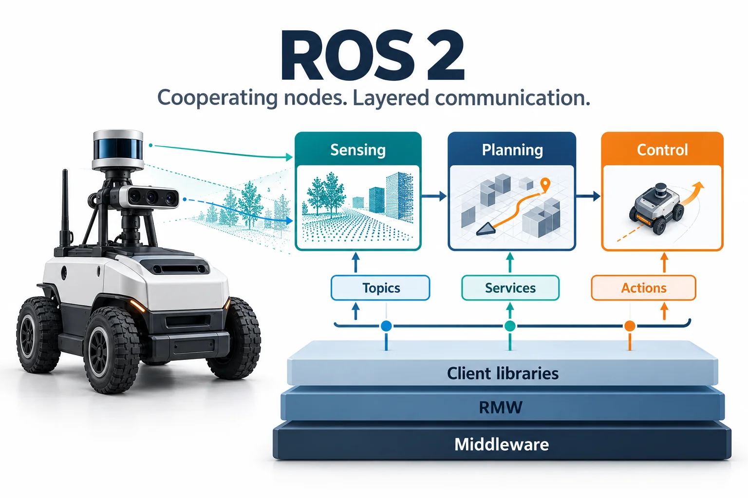
ROS 2 organizes functions such as sensing, planning, and control into cooperating nodes, and provides a foundation for communication, scheduling, and system integration. Understanding how nodes exchange data, and what the client, executor, and middleware are each responsible for, is the starting point for reading this architectural guide.
Reading diagrams: scroll horizontally inside wide Mermaid diagrams to see all details at a readable size. Keyboard users can focus a diagram and use the arrow keys.
1. From ROS 1 to ROS 2
1.1 Why a rewrite
ROS (Robot Operating System) was born in 2007 between the Stanford University Artificial Intelligence Laboratory (STAIR project) and Willow Garage. Its original intention was to provide an open source robot software rapid prototyping platform for the academic community. As robotics technology moves from the laboratory to industrial automation, commercial services, autonomous driving, and humanoid embodied intelligence, the design limitations of ROS 1 have become increasingly prominent:
- Centralized single point of failure (Single Point of Failure): ROS 1 strong dependency
roscore(Master node) running on fixed IP/port. If the Master crashes or a network partition occurs, the node discovery and communication registration of the entire robot system will be completely paralyzed. - lacks determinism and hard/soft real-time support: The bottom layer of ROS 1 is based on standard TCP/UDP sockets. The operating system has no priority control for scheduling and cannot meet the microsecond/millisecond level deterministic real-time control requirements of industrial controllers and underlying motor drivers.
- Poor network adaptability and no native encryption security mechanism: TCPROS/UDPROS has a high packet loss rate and fragile reconnection mechanism in wireless lossy networks (Wi-Fi, 4G/5G, cross-segment); the communication link is plain text transmission, and there is no identity authentication and access control mechanism.
- Multi-machine collaboration and multi-robot clusters are highly complex: ROS 1 multi-machine communication requires strict configuration
ROS_MASTER_URIandROS_IP, and lacks flexible domain isolation and multi-machine discovery management solutions. - embedded microcontroller isolation: cannot run directly on microcontrollers (MCU/DSP/RTOS) with limited computing and memory, and can usually only be inefficiently bridged through fragile serial port protocols (such as
rosserial).
To solve these problems, Open Robotics did not patch ROS 1; instead it redesigned ROS 2 on top of the industrial standard DDS (Data Distribution Service).
flowchart TB
    subgraph ROS1["ROS 1: relies on the central roscore"]
        direction LR
        N1["Sensor node"] -->|Register / query| Master["roscore (Master)<br/>single point of failure"]
        N2["Algorithm node"] -->|Register / query| Master
        N3["Control node"] -->|Register / query| Master
        style Master fill:#ffe3e3,stroke:#c92a2a,color:#7a1c1c
    end

    subgraph ROS2["ROS 2: nodes discover each other through DDS"]
        direction LR
        P1["Sensor node"] <-->|RTPS discovery| P2["Algorithm node"]
        P2 <-->|Matched by QoS| P3["Control node"]
        style ROS2 fill:#eefaf0,stroke:#2b8a3e
    end

    ROS1 ~~~ ROS2
Figure: In ROS 1, nodes must register with roscore before they can find each other; in ROS 2, nodes discover each other directly through DDS/RTPS, with no central node.
1.2 ROS 1 vs. ROS 2
| Dimensions | ROS 1 (Noetic / Melodic) | ROS 2 (Humble / Iron / Jazzy) | Core Values/Industrial Impact |
|---|---|---|---|
| Network topology | Centralized coordination based on Master (roscore) |
Fully distributed decentralization based on DDS RTPS | Eliminate single points of failure and support large-scale cluster dynamic networking |
| Underlying communication | Custom TCPROS / UDPROS protocol | OMG industrial grade DDS standard (Fast DDS, Cyclone DDS, Connext, etc.) | Reuse military/aerospace grade mature data distribution base |
| Quality of Service (QoS) | Only supports simple TCP reliable transmission and UDP best-effort transmission | Complete QoS policy (Reliability, Durability, History, Deadline, etc.) | Precisely adapts to the requirements of high-frequency, low-latency sensors and high-reliability control |
| Cross-process/intra-process communication | Socket serialization copy; Nodelet intra-process sharing (API split) | Unified Component container; native support for borrowing pointers zero-copy (Zero-Copy IPC) | Greatly reduces the CPU usage of hundreds-of-megabytes high-resolution point-cloud and 4K image transmission |
| node lifecycle | Stateless black box; nodes are initialized out of order. | Native managed lifecycle node (Lifecycle Managed Nodes) | Ensure deterministic controlled startup sequence and fault degradation of sensor drivers, algorithms, and executors |
| real-time support | Linux general-purpose kernel; no real-time guarantees | Support hard real-time OS such as Linux PREEMPT_RT, QNX, VxWorks, etc., with zero memory dynamic allocation API | Meet microsecond-level closed-loop motion control requirements |
| embedded support | Only through rosserial serial port translation |
micro-ROS natively supports STM32, ESP32, Zephyr, and FreeRTOS | MCU microcontroller seamlessly acts as a first-class ROS 2 node |
| Safety mechanism | No security verification, naked network | SROS2 Specification: DDS-Security Authentication, Access Control List (ACL), TLS/AES Encryption | Meet commercial robot security compliance and cyber attack resistance standards |
| parameter system | Globally unified Parameter Server | Node is a private and independent Parameter instance that supports runtime strong type constraints and event monitoring. | Avoid parameter namespace pollution and support dynamic reconfiguration interception |
| Multi-platform build | Strong dependency Ubuntu Linux / CMake (catkin) |
Native support for Linux, Windows, macOS (colcon + ament) |
Lowering the threshold for cross-platform industrial software migration |
1.3 Distributions and support
ROS 2 releases a new distribution every May, aligned with Ubuntu: even-numbered years bring a long-term support (LTS) release supported for five years, and odd-numbered years bring a regular release supported for about a year and a half.
| Distribution | Released | Target platform | Type | Support status (as of 2026-10) |
|---|---|---|---|---|
| Foxy Fitzroy | 2020-05 | Ubuntu 20.04 | LTS | End of life |
| Galactic Geochelone | 2021-05 | Ubuntu 20.04 | Regular | End of life |
| Humble Hawksbill | 2022-05 | Ubuntu 22.04 | LTS | Supported until 2027-05; most widely deployed |
| Iron Irwini | 2023-05 | Ubuntu 22.04 | Regular | End of life |
| Jazzy Jalisco | 2024-05 | Ubuntu 24.04 | LTS | Supported until 2029-05 |
| Kilted Kaiju | 2025-05 | Ubuntu 24.04 | Regular | Nearing end of life |
| Lyrical Luth | 2026-05 | Ubuntu 26.04 | LTS | Supported until 2031-05; newest LTS |
Selection advice
- Production deployment: choose Humble (Ubuntu 22.04) or Jazzy (Ubuntu 24.04); ecosystem packages such as Nav2, MoveIt 2, and ros2_control support them most completely. New projects can evaluate Lyrical, but first confirm that the ecosystem packages they depend on have been released for it.
- Cutting-edge research and development: use the newest LTS or Rolling to get new features such as executor performance improvements and Type Adaptation earlier.
2. Layered architecture and DDS
2.1 Software layers
ROS 2 uses a layered design that decouples upper-layer algorithm code from the underlying transport middleware: switching middleware requires no change to application code.
flowchart TB
    subgraph UserLayer["User application layer"]
        AppCpp["C++ nodes / components"]
        AppPy["Python nodes / scripts"]
        AppRust["Rust nodes"]
    end

    subgraph ClientLayer["Client library layer"]
        RCLCPP["rclcpp<br/>(C++)"]
        RCLPY["rclpy<br/>(Python)"]
        RCLC["rclc<br/>(C / micro-ROS)"]
        RCL["rcl<br/>(common pure C core)"]
        RCUTILS["rcutils /<br/>rmw_implementation"]
    end

    subgraph RMWLayer["Middleware interface layer (RMW)"]
        RMW_API["rmw: unified C interface<br/>(Publisher / Subscriber / Service / WaitSet)"]
    end

    subgraph DDSLayer["Middleware implementation layer"]
        RMW_Fast["Fast DDS"]
        RMW_Cyclone["Cyclone DDS"]
        RMW_Connext["Connext DDS"]
        RMW_Zenoh["Zenoh"]
    end

    subgraph TransportLayer["Transport layer"]
        UDP["UDP multicast / unicast"]
        SHM["Shared memory<br/>(POSIX / Iceoryx)"]
        UART["Serial / CAN / USB"]
    end

    AppCpp --> RCLCPP
    AppPy --> RCLPY
    AppRust --> RCL
    RCLCPP --> RCL
    RCLPY --> RCL
    RCLC --> RCL
    RCL --> RCUTILS --> RMW_API
    RMW_API --> RMW_Fast
    RMW_API --> RMW_Cyclone
    RMW_API --> RMW_Connext
    RMW_API --> RMW_Zenoh
    RMW_Fast --> UDP & SHM
    RMW_Cyclone --> UDP & SHM
    RMW_Connext --> UDP & SHM
    RMW_Zenoh --> UDP & UART
The middleware implementation layer in the diagram corresponds to the four packages rmw_fastrtps_cpp, rmw_cyclonedds_cpp, rmw_connextdds, and rmw_zenoh_cpp; Section 2.3 compares their trade-offs.
Key component responsibilities
rcl(ROS Client Library): a common logic layer written in pure C that handles language-independent functions such as parameter parsing, the node graph, logging, and clocks, so that client libraries for C++, Python, and other languages behave consistently.rmw(ROS Middleware): a unified C interface that defines operations such as publishing, subscribing, wait sets, and QoS mapping; upper-layer code does not need to know which middleware is used underneath.rosidl: Interface Definition Language (IDL) generator, which automatically generates.msg,.srv, and.actioninto native structures and serialization/deserialization codes in C, C++, and Python.
2.2 How DDS works
DDS is the Object Management Organization ( OMG ), the core of which is Data-Centric Publish-Subscribe Model (DCPS, Data-Centric Publish-Subscribe) .
flowchart LR
    subgraph Domain["DDS communication domain (Domain ID: 0~101)"]
        subgraph Participant1["DomainParticipant (Node 1)"]
            Pub["Publisher"] --> DW["DataWriter"]
        end

        subgraph GlobalDataSpace["global data space (Global Data Space)"]
            TopicData[("Topic: /camera/image_raw<br/>Type: sensor_msgs/Image<br/>QoS: SensorData Profile")]
        end

        subgraph Participant2["DomainParticipant (Node 2)"]
            DR["DataReader"] --> Sub["Subscriber"]
        end

        DW ==>|"write (Write)"| TopicData
        TopicData ==>|"read (Take/Read)"| DR
    end
RTPS discovery
When DDS nodes are started in the LAN, they can automatically discover each other without Master coordination. It contains two Stages:
- SPDP (Simple Participant Discovery Protocol): After the node starts, it periodically sends multicast heartbeat packets to the predetermined port (the multicast address
239.255.0.1calculated based on the Domain ID) to announce its Participant GUID, IP address and transmission port. - SEDP (Simple Endpoint Discovery Protocol): When Participants discover each other, they establish a reliable unicast connection and exchange the DataWriter / DataReader details (Topic name, data type, QoS configuration) contained in each other. If the QoS matching is successful, a point-to-point data channel is established at the bottom layer.
sequenceDiagram
    autonumber
    participant A as node A (Publisher)
    participant Multicast as LAN multicast network segment (SPDP)
    participant B as node B (Subscriber)

    Note over A: node A start (Domain 0)
    A->>Multicast: broadcast SPDP heartbeat: "i am NodeA, IP:Port=..."
    Multicast->>B: forward SPDP discovery message
    Note over B: node B record NodeA exist
    B->>A: unicast reply SPDP heartbeat: "i am NodeB, IP:Port=..."

    rect rgb(240, 248, 255)
        Note over A,B: enter SEDP endpoint matching phase (Unicast exchange metadata)
        A->>B: SEDP declare: "i have DataWriter, topic: /scan, QoS: BestEffort"
        B->>A: SEDP declare: "i have DataReader, topic: /scan, QoS: BestEffort"
        Note over A,B: Check QoS Compatibility: Match successful!
    end

    rect rgb(240, 255, 240)
        Note over A,B: Establish a direct data flow channel
        loop Sensor data cycle transmission
            A->>B: Send lidar PointCloud / LaserScan packet
        end
    end
2.3 RMW implementations
| middleware (RMW) | Supplier/Licensing | Advantages and core features | Disadvantages/Notes | Recommended application scenarios |
|---|---|---|---|---|
Fast DDS (rmw_fastrtps_cpp) |
eProsima (Apache-2.0) | ROS 2 official default implementation; complete functions, built-in high-performance shared memory (SHM) transmission, and supports Discovery Server | Multicast packet loss in a weak Wi-Fi network environment can easily lead to slow discovery | Default general robot development, stand-alone simulation, high-performance stand-alone deployment |
Cyclone DDS (rmw_cyclonedds_cpp) |
Eclipse (EPL-2.0) | The architecture is lightweight and the code is refined; it is extremely robust to Wi-Fi jitter networks, has high throughput and extremely low latency. | Shared memory configuration is more complex (requires Iceoryx) | Autonomous driving, multi-machine distributed systems, wireless mobile robots |
Connext DDS (rmw_connextdds) |
RTI (commercial license) | Industrial/military grade certification, support for safety-critical systems (ISO 26262 ASIL-D, DO-178C), complete debugging toolset | Commercial charging closed source | Aerospace, medical surgical robots, automotive grade autonomous driving systems |
Zenoh (rmw_zenoh_cpp) |
ZettaScale (Apache-2.0) | Abandon complex RTPS and adopt a minimalist protocol; zero multicast storm, naturally supporting cross-public network/4G/5G/cloud-edge collaborative communication | Still evolving rapidly, the ecosystem tool chain is gradually maturing. | Cross-wide area network (WAN) vehicle-cloud interconnection and large-scale robot cluster management |
# Dynamic switching of environment variables RMW(No need to recompile code)
export RMW_IMPLEMENTATION=rmw_cyclonedds_cpp
ros2 run my_pkg my_node

# Verify currently using RMW realize
ros2 doctor --report | grep middleware
2.4 Multi-machine and Domain ID
In order to isolate nodes of different robots or teams under the same LAN switch, ROS 2 provides ROS_DOMAIN_ID. Valid values are 0 to 232; use 0 to 101, which avoids conflicts with the operating system’s ephemeral ports on every platform.
# Set the domain ID for this robot in ~/.bashrc
export ROS_DOMAIN_ID=42

# Discovery range (Jazzy and later): SUBNET allows LAN communication, LOCALHOST restricts it to this machine
export ROS_AUTOMATIC_DISCOVERY_RANGE=SUBNET
# Humble and earlier use ROS_LOCALHOST_ONLY=0/1 for the same purpose (deprecated since Jazzy)
DDS port formula Each Domain ID occupies a fixed range of UDP ports: \(\text{Port} = 7400 + 250 \times \text{DomainID} + \text{Offset}\) Devices on the same network segment with the same
ROS_DOMAIN_IDdiscover each other’s nodes automatically.
3. Communication primitives
ROS 2 abstracts all software decoupled interactions into five communication primitives. Choosing the correct communication method is the first principle of system architecture design.
mindmap
  root((ROS 2 communication primitives))
    Topics
      One-way asynchronous broadcast
      publish / Subscription model
      Applicable: high-frequency sensor flow, control instructions
    Services
      Synchronous / asynchronous request-response
      client / server mode
      Applicable: short-term triggering, mode switching, parameter query
    Actions
      Preemptive long-running asynchronous tasks
      contains Goal / Feedback / Result
      Applicable to: Navigation, robotic arm trajectory execution
    Parameters
      node private runtime configuration
      Support dynamic changes and verification
      Applicable:PID Gain, threshold, sensor extrinsics
    Lifecycle
      Controlled state transitions
      Unconfigured -> Inactive -> Active
      Applicable: deterministic drive startup, fault protection
3.1 Choosing a primitive
flowchart TD
    Start([Need inter-module communication?]) --> Q1{Continuous or high-frequency data?}
    Q1 -->|"Yes"| NodeTopic["Use topic (Topic)<br/>Publish-subscribe / asynchronous decoupling"]
    Q1 -->|"No"| Q2{Need a response from the peer?}
    Q2 -->|"No"| NodeTopic
    Q2 -->|"Yes"| Q3{Does the task take more than 100ms?}
    Q3 -->|"No: short operation"| NodeService["Use service (Service)<br/>Request-response / short operation"]
    Q3 -->|"Yes: long or cancellable task"| NodeAction["Use action (Action)<br/>Progress feedback / cancellation support"]
    Start --> Q4{Algorithm configuration or runtime parameter change?}
    Q4 -->|"Yes"| NodeParam["Use parameters (Parameter)<br/>YAML configuration / validation callbacks"]
3.2 Topics
Communication principles
topic is a many-to-many publish-subscribe (Pub/Sub) channel. The publisher pushes the data to the DDS domain, and the subscriber receives the data according to the QoS policy. The two parties are completely decoupled in lifecycle and network topology.
flowchart LR
    subgraph Publishers["publisher cluster"]
        P1["Lidar driver"]
        P2["Depth camera point cloud"]
        P3["Wheel odometry driver"]
    end

    subgraph Channel["DDS topic bus"]
        T1(["/scan<br/>(sensor_msgs/LaserScan)"])
        T2(["/odom<br/>(nav_msgs/Odometry)"])
    end

    subgraph Subscribers["subscriber cluster"]
        S1["SLAM Map node"]
        S2["local obstacle avoidance algorithm"]
        S3["RViz2 visualization"]
    end

    P1 --> T1
    P2 --> T1
    P3 --> T2
    T1 --> S1 & S2 & S3
    T2 --> S1 & S2
C++ implementation (rclcpp)
#include <chrono>
#include <memory>
#include <string>
#include "rclcpp/rclcpp.hpp"
#include "std_msgs/msg/string.hpp"

using namespace std::chrono_literals;

class RobustPublisher : public rclcpp::Node {
public:
    RobustPublisher() : Node("robust_publisher_node"), count_(0) {
        // Create sensor-specific BestEffort QoS
        rclcpp::QoS qos_profile(rclcpp::KeepLast(10));
        qos_profile.best_effort();
        qos_profile.durability_volatile();

        publisher_ = this->create_publisher<std_msgs::msg::String>("/telemetry_data", qos_profile);
        timer_ = this->create_wall_timer(100ms, std::bind(&RobustPublisher::timer_callback, this));

        RCLCPP_INFO(this->get_logger(), "High-frequency publisher node has been started (10Hz)...");
    }

private:
    void timer_callback() {
        auto message = std_msgs::msg::String();
        message.data = "Telemetry Frame #" + std::to_string(count_++);
        publisher_->publish(message);
    }

    rclcpp::TimerBase::SharedPtr timer_;
    rclcpp::Publisher<std_msgs::msg::String>::SharedPtr publisher_;
    size_t count_;
};

int main(int argc, char* argv[]) {
    rclcpp::init(argc, argv);
    rclcpp::spin(std::make_shared<RobustPublisher>());
    rclcpp::shutdown();
    return 0;
}
Python implementation (rclpy)
#!/usr/bin/env python3
import rclpy
from rclpy.node import Node
from rclpy.qos import QoSProfile, ReliabilityPolicy, HistoryPolicy
from std_msgs.msg import String

class RobustSubscriber(Node):
    def __init__(self):
        super().__init__('robust_subscriber_node')

        # Definition matching publisher QoS Configuration
        qos = QoSProfile(
            history=HistoryPolicy.KEEP_LAST,
            depth=10,
            reliability=ReliabilityPolicy.BEST_EFFORT
        )

        self.subscription = self.create_subscription(
            String,
            '/telemetry_data',
            self.listener_callback,
            qos
        )
        self.get_logger().info('The subscribing node is ready, waiting for telemetry data...')

    def listener_callback(self, msg: String):
        self.get_logger().info(f'telemetry frame received: "{msg.data}"')

def main(args=None):
    rclpy.init(args=args)
    node = RobustSubscriber()
    try:
        rclpy.spin(node)
    except KeyboardInterrupt:
        pass
    finally:
        node.destroy_node()
        rclpy.shutdown()

if __name__ == '__main__':
    main()
3.3 Services
Communication principles
The service is a point-to-point client-server (Client/Server) communication model. The client sends Request, and the server returns Response after calculation.
Caution: Do not wait synchronously for a service result inside a callback run by a single-threaded executor (for example, calling
get()on the future returned byasync_send_request(), orclient.call()in Python). The wait occupies the only thread, so the response callback never runs and the node deadlocks. Call the service asynchronously and handle the result in the future’s completion callback.
sequenceDiagram
    autonumber
    participant C as Service Client (control node)
    participant S as Service Server (Motor servo drive)

    C->>S: send SetBool.Request {data: true}
    Note over C: non-blocking wait (async) / Register Future callback
    Note over S: Execute enable power-on logic...
    S-->>C: Return SetBool.Response {success: true, message: "Motor Ready"}
    Note over C: Future Completed, perform subsequent business
3.4 Actions
Communication principles
Actions are for long-running asynchronous tasks, such as navigating a base from point A to point B or having a robot arm perform a grasp. Underneath, an Action consists of three services and two topics:
- Goal (service): The client sends a goal, and the server accepts or rejects it.
- Cancel (service): The client can request cancellation at any time, and the server safely interrupts the task.
- Result (service): Returns the final outcome (succeeded, aborted, or canceled) when the task ends.
- Feedback (topic): Streams progress during execution, such as the current pose or remaining distance.
- Status (topic): Broadcasts the current state of each goal.
stateDiagram-v2
    [*] --> ACCEPTED: client sends Goal, server accepts
    ACCEPTED --> EXECUTING: Start executing task logic

    state EXECUTING {
        [*] --> PublishingFeedback: Keep sending Feedback topic
        PublishingFeedback --> PublishingFeedback: Compute intermediate states
    }

    EXECUTING --> SUCCEEDED: Complete your goals successfully (succeed)
    EXECUTING --> ABORTED: Encountered an unrecoverable exception (abort)
    EXECUTING --> CANCELING: Receive client CancelGoal Request

    CANCELING --> CANCELED: Safely stop an executor (canceled)

    SUCCEEDED --> [*]
    ABORTED --> [*]
    CANCELED --> [*]
Action interface definition
# 1. Target (Goal)
geometry_msgs/PoseStamped pose
string behavior_tree
---
# 2. Final result (Result)
std_msgs/Empty result
int16 error_code
---
# 3. Real time feedback (Feedback)
geometry_msgs/PoseStamped current_pose
builtin_interfaces/Duration navigation_time
builtin_interfaces/Duration estimated_time_remaining
int16 number_of_recoveries
float32 distance_remaining
3.5 Parameters
In ROS 2, parameters are private data items bound to a specific node instance, supporting strong type verification, range constraints and dynamic modification callback interception.
// C++ Declare parameters with descriptors and dynamic verification
rcl_interfaces::msg::ParameterDescriptor desc;
desc.description = "Robot maximum linear speed limit (m/s)";
desc.floating_point_range.resize(1);
desc.floating_point_range[0].from_value = 0.0;
desc.floating_point_range[0].to_value = 2.5;
desc.floating_point_range[0].step = 0.05;
this->declare_parameter("max_linear_velocity", 1.0, desc);
// Register dynamic parameter change interception callback (OnSetParametersCallback)
params_callback_handle_ = this->add_on_set_parameters_callback(
[this](const std::vector<rclcpp::Parameter> ¶meters) {
rcl_interfaces::msg::SetParametersResult result;
result.successful = true;
for (const auto ¶m : parameters) {
if (param.get_name() == "max_linear_velocity") {
if (param.as_double() > 2.0) {
result.successful = false;
result.reason = "Safety protection trigger: the actual vehicle line speed cannot exceed 2.0 m/s";
} else {
RCLCPP_INFO(this->get_logger(), "The speed cap is updated to: %.2f", param.as_double());
}
}
}
return result;
}
);
4. Quality of Service (QoS)
QoS (Quality of Service) is the most important communication improvement of ROS 2 over ROS 1: the underlying transport behavior can be configured separately according to the characteristics of each data flow.
4.1 Core policies
| Policy | Values | Meaning |
|---|---|---|
| Reliability | RELIABLE / BEST_EFFORT |
Retransmit after packet loss; or send on a best-effort basis and allow loss |
| Durability | VOLATILE / TRANSIENT_LOCAL |
Keep no history; or keep the latest N messages for subscribers that join later |
| History & Depth | KEEP_LAST(N) / KEEP_ALL |
Keep only the latest N messages; or keep all of them up to resource limits |
| Liveliness & Lease | AUTOMATIC / MANUAL_BY_TOPIC |
The middleware reports liveliness automatically; or the publisher asserts it explicitly |
| Deadline | Duration | Maximum interval between consecutive messages; exceeding it triggers an event |
| Lifespan | Duration | Messages older than their lifespan are no longer delivered |
4.2 Compatibility rules
Request vs. Offer principle
The QoS offered by the publisher must be no weaker than the QoS requested by the subscriber; otherwise the two ends do not connect. The program keeps running and the subscriber simply receives no data, leaving at most a QoS-incompatibility warning in the log; compare the QoS of both ends with
ros2 topic info -vto diagnose it.
flowchart LR
    subgraph Publisher["Publishing side (Offered QoS)"]
        PubRel["Reliability: BEST_EFFORT"]
    end

    subgraph Subscriber["Subscriber (Requested QoS)"]
        SubRel["Reliability: RELIABLE"]
    end

    Publisher -.->|"❌ Match failed! Silent disconnect"| Subscriber

    style Publisher fill:#ffe3e3,stroke:#e03131
    style Subscriber fill:#ffe3e3,stroke:#e03131
Compatibility matrix
| publisher (Offered) | subscriber (Requested) | Match results | Description |
|---|---|---|---|
| RELIABLE | RELIABLE | ✅ Compatible | Reliable transmission across the entire link (automatic retransmission of lost packets) |
| RELIABLE | BEST_EFFORT | ✅ Compatible | The publisher can provide high guarantee, and the subscriber accepts a weaker guarantee |
| BEST_EFFORT | BEST_EFFORT | ✅ Compatible | Best effort transmission, low latency, packet loss allowed |
| BEST_EFFORT | RELIABLE | ❌ Incompatible | The subscriber requires reliability, but the publisher cannot guarantee it. cannot communicate |
| TRANSIENT_LOCAL | VOLATILE | ✅ Compatible | The subscriber does not require historical data and can receive real-time data normally. |
| VOLATILE | TRANSIENT_LOCAL | ❌ Incompatible | Subscriber requires historical map, but publisher is not cached, cannot communicate |
4.3 Common profiles
| Scenario application | Reliability | Durability | History (Depth) | design considerations |
|---|---|---|---|---|
high frequency raw camera image / lidar (/image_raw, /scan) |
BEST_EFFORT |
VOLATILE |
KEEP_LAST (1~5) |
Pursuing extremely low latency, discarding an old image has no impact and avoids queue backlog |
Chassis control command (/cmd_vel) |
RELIABLE |
VOLATILE |
KEEP_LAST (10) |
Control instructions must be delivered accurately, and frame loss causing loss of control is prohibited. |
static map / parameter event (/map, /robot_description) |
RELIABLE |
TRANSIENT_LOCAL |
KEEP_LAST (1) |
Similar to the Latch mechanism of ROS 1, the SLAM/Nav2 node started later can obtain the full map as soon as it goes online. |
high reliability status alarm (/emergency_stop) |
RELIABLE |
TRANSIENT_LOCAL |
KEEP_ALL |
Emergency stop and failure events must never be lost |
5. Executors and zero-copy
5.1 Executors
In ROS 2, callbacks (Timer, Subscription, Service, Action) do not run on background threads by themselves; an Executor takes ready events from the underlying WaitSet and schedules them.
| Executor | Scheduling | Advantages | Costs and caveats |
|---|---|---|---|
SingleThreadedExecutor |
One thread runs all ready callbacks in order | No concurrency contention; thread-safe by construction | Any long-running callback holds up every later event |
MultiThreadedExecutor |
A thread pool runs ready callbacks in parallel | Uses multiple cores to improve responsiveness and throughput | Concurrency must be controlled with callback groups (see Section 5.2) to avoid data races |
EventsExecutor |
Woken directly by middleware events instead of polling the WaitSet | Low idle CPU overhead; saves power under light load | Provided as an experimental feature since Iron; check support in the version you use |
5.2 Callback groups and deadlocks
In order to finely control concurrent permissions in MultiThreadedExecutor, ROS 2 provides two types of callback groups:
MutuallyExclusiveCallbackGroup(mutually exclusive group, default): All callback functions in this group can only be executed by one thread at the same time.ReentrantCallbackGroup(reentrant group): Different callbacks within the group (even multiple triggers of the same callback) can be executed in parallel by multiple threads.
flowchart LR
    subgraph NodeInstance["node internal structure"]
        subgraph Group1["MutuallyExclusive Group (mutually exclusive group)"]
            CB1["Sensor status polling Timer (100Hz)"]
            CB2["Motor enable Service"]
        end

        subgraph Group2["Reentrant Group (reentrant group)"]
            CB3["High frequency image processing subscriber"]
            CB4["point cloud filter subscriber"]
        end
    end

    Pool["MultiThreadedExecutor thread pool"]
    Pool -.-> Group1
    Pool ==> Group2
Classic deadlock scenario
A subscription callback synchronously waits for a service response, while the callback that handles the response belongs to the same default mutually exclusive callback group. The subscription callback holds execution while it waits, the response callback never gets a turn, and the node hangs.
Solutions (use either one or both):
- Put the waiting callback and the response-handling callback in different callback groups, and use
MultiThreadedExecutor.- Do not block inside a callback; call the service asynchronously and handle the result in the future’s completion callback.
5.3 Components and zero-copy IPC
Traditional multi-node systems use a multi-process model, so a message between nodes passes through user-space memory → serialization → kernel socket → deserialization → destination user-space memory. For data streams of hundreds of megabytes per second, such as 4K images or 3D lidar point clouds, the CPU and memory-bandwidth overhead is large.
ROS 2 Components compile multiple nodes into dynamic libraries (.so / .dll) that are loaded into the same ComposableNodeContainer process at runtime. With intra-process communication enabled, publishing a message as a std::unique_ptr transfers pointer ownership directly without copying the data (zero-copy IPC).
flowchart TB
    subgraph Traditional["Multiple processes: every message is serialized and copied"]
        direction LR
        P1["Camera driver node"] -->|Serialize| K["Kernel socket / DDS"]
        K -->|Copy + deserialize| P2["Detection node"]
    end

    subgraph Container["Component container: pass pointers within one process"]
        direction LR
        C1["Camera component"] ==>|"Transfer unique_ptr<br/>no data copy"| C2["Detection component"]
    end

    Traditional ~~~ Container
C++ zero-copy publisher example
#include "rclcpp/rclcpp.hpp"
#include "sensor_msgs/msg/point_cloud2.hpp"

using namespace std::chrono_literals;

class ZeroCopyPointCloudPublisher : public rclcpp::Node {
public:
    // Load the component with intra-process communication enabled: NodeOptions().use_intra_process_comms(true)
    explicit ZeroCopyPointCloudPublisher(const rclcpp::NodeOptions & options)
    : Node("zero_copy_publisher", options) {
        pub_ = this->create_publisher<sensor_msgs::msg::PointCloud2>("/points", 10);
        timer_ = this->create_wall_timer(33ms, std::bind(&ZeroCopyPointCloudPublisher::publish_cloud, this));
    }

private:
    void publish_cloud() {
        // Use unique_ptr Construct exclusive ownership message
        auto cloud_msg = std::make_unique<sensor_msgs::msg::PointCloud2>();

        // Populate large point cloud data buffer ...
        cloud_msg->header.stamp = this->now();
        cloud_msg->header.frame_id = "lidar_frame";
        cloud_msg->width = 1920;
        cloud_msg->height = 1080;
        cloud_msg->data.resize(cloud_msg->width * cloud_msg->height * 16);

        // Use std::move Transfer ownership, triggering direct exchange of underlying intra-process pointers
        pub_->publish(std::move(cloud_msg));
    }

    rclcpp::Publisher<sensor_msgs::msg::PointCloud2>::SharedPtr pub_;
    rclcpp::TimerBase::SharedPtr timer_;
};
6. Lifecycle nodes
On a real robot, an uncontrolled node startup order can cause accidents, for example the navigation algorithm publishing velocity commands before the lidar or base driver has finished validating its parameters. ROS 2 therefore provides the Lifecycle Node (managed lifecycle node): a node starts up through an explicit state machine, and an external manager decides when to activate it.
6.1 State machine
stateDiagram-v2
    [*] --> Unconfigured: Constructor instantiation

    Unconfigured --> Inactive: on_configure()<br/>Load parameters, allocate resources
    Inactive --> Unconfigured: on_cleanup()<br/>Release resources

    Inactive --> Active: on_activate()<br/>Enable output
    Active --> Inactive: on_deactivate()<br/>Pause output

    Active --> Finalized: on_shutdown()
    Inactive --> Finalized: on_shutdown()
    Unconfigured --> Finalized: on_shutdown()

    Active --> ErrorProcessing: Catching runtime exceptions
    Inactive --> ErrorProcessing: Configuration verification failed
    Unconfigured --> ErrorProcessing: Hardware connection abnormality

    ErrorProcessing --> Unconfigured: on_error() Processed successfully
    ErrorProcessing --> Finalized: on_error() Processing failed

    Finalized --> [*]: Destruct and destroy node
State meanings
Unconfigured(not configured): The node is loaded, but the parameters are not read and the hardware device is not connected.Inactive(inactive): The configuration is loaded, the Publisher and Subscriber are established, but the Publisher is in a silent state (does not broadcast any messages to DDS), and the execution is suspended.Active(active state): The system is operating normally, all callbacks are activated, and the main control loop is executed.Finalized(terminal status): Resources are completely released and the process is ready to exit.
7. TF2 transforms
There are a large number of geometric coordinate frames in the robot system (world, base, lidar, end-effector, and camera optical frames). TF2 (Transform Library 2) is responsible for maintaining the space-time transformation tree (Transform Tree) within the entire robot lifecycle.
7.1 Standard frames
According to the official ROS specification REP 105, mobile robots must strictly follow the tree-like single-parent topology:
flowchart TB
    earth["earth (global earth coordinate frame / ECEF WGS-84)"]
    map["map (Map global coordinate frame / Fixed origin / discrete corrections)"]
    odom["odom (odometry local coordinate frame / Continuous / subject to drift)"]
    base_footprint["base_footprint (Base projection onto the ground / Z=0)"]
    base_link["base_link (Robot body rigid body geometric center)"]

    subgraph Sensors["Sensor extrinsic frames (static TF broadcast)"]
        laser_link["laser_link (lidar)"]
        camera_link["camera_link (camera reference frame)"]
        camera_optical["camera_optical_frame (Optical frame: X right / Y down / Z forward)"]
        imu_link["imu_link (IMU inertial unit)"]
    end

    earth -.->|"GPS / RTK localization broadcast"| map
    map -->|"SLAM / AMCL localization broadcast (Eliminate drift)"| odom
    odom -->|"Wheel / visual odometry broadcasts"| base_footprint
    base_footprint --> base_link
    base_link ==> laser_link
    base_link ==> camera_link
    camera_link ==> camera_optical
    base_link ==> imu_link

    style map fill:#d0ebff,stroke:#1971c2
    style odom fill:#ffe8cc,stroke:#d9480f
    style base_link fill:#d3f9d8,stroke:#2b8a3e
- REP 103 Coordinate axis definition convention:
- Robot body: FLU (Forward-Left-Up): $X$ axis is forward, $Y$ axis is to the left, $Z$ axis is upward.
- Camera optical coordinate frame: RDF (Right-Down-Forward): $X$ axis is to the right, $Y$ axis is downward, and $Z$ axis is forward (sight direction).
7.2 Dynamic vs. static TF
/tf(dynamic transformation): Broadcast the changing relative pose (such asodom -> base_link) at a fixed frequency (such as 50Hz)./tf_static(static extrinsics): only broadcast once when the system starts or the sensor extrinsic calibration is completed. It usesTRANSIENT_LOCALQoS underneath, so nodes that start later still receive it without periodic rebroadcasting, which saves CPU and bandwidth.
// C++ Monitor and query the transformation relationship between any two coordinate frames at a certain moment in history
#include "tf2_ros/buffer.h"
#include "tf2_ros/transform_listener.h"

auto tf_buffer = std::make_unique<tf2_ros::Buffer>(this->get_clock());
auto tf_listener = std::make_shared<tf2_ros::TransformListener>(*tf_buffer);

try {
    // Most blocked 100ms Query map Arrive laser_link latest transformation of
    geometry_msgs::msg::TransformStamped transform = tf_buffer->lookupTransform(
        "map", "laser_link",
        tf2::TimePointZero,
        std::chrono::milliseconds(100)
    );
    RCLCPP_INFO(this->get_logger(), "Radar global coordinates on the map: x=%.2f, y=%.2f",
                transform.transform.translation.x, transform.transform.translation.y);
} catch (const tf2::TransformException & ex) {
    RCLCPP_WARN(this->get_logger(), "TF Transform query failed: %s", ex.what());
}
8. URDF and Xacro
8.1 Robot description system
- URDF (Unified Robot Description Format): Use XML to describe the robot’s links, joints, physical collision bodies and inertia tensors.
- Xacro (XML Macros): Evolved from the defect that URDF does not support variables, macros, inclusions and mathematical operations, it is the standard way of modeling modern robots.
flowchart LR
    subgraph Modeling["Robot modeling and publishing data flow"]
        XACRO["robot.xacro<br/>(Parametric macros and mathematical expressions)"] -->|"xacro parser"| URDF["robot.urdf (Standard XML)"]
        URDF --> RSP["robot_state_publisher"]
        JSP["joint_state_publisher<br/>or ros2_control<br/>(publish /joint_states)"] --> RSP
        RSP -->|"Broadcast global static and dynamic TF"| TF_Tree["/tf_static & /tf coordinate tree"]
        TF_Tree --> RViz["RViz2 / Nav2 / MoveIt 2"]
    end
8.2 Xacro macro example
<?xml version="1.0"?>
<robot xmlns:xacro="http://www.ros.org/wiki/xacro" name="industrial_diff_bot">

  <!-- constant definition -->
  <xacro:property name="wheel_radius" value="0.10" />
  <xacro:property name="wheel_width" value="0.05" />
  <xacro:property name="wheel_mass" value="2.5" />
  <xacro:property name="track_width" value="0.45" />

  <!-- Macro: Parameterized definition of power drive wheels -->
  <xacro:macro name="drive_wheel" params="prefix side_sign">
    <link name="${prefix}_wheel_link">
      <visual>
        <origin xyz="0 0 0" rpy="${pi/2} 0 0"/>
        <geometry>
          <cylinder radius="${wheel_radius}" length="${wheel_width}"/>
        </geometry>
        <material name="black"><color rgba="0.1 0.1 0.1 1.0"/></material>
      </visual>
      <collision>
        <origin xyz="0 0 0" rpy="${pi/2} 0 0"/>
        <geometry>
          <cylinder radius="${wheel_radius}" length="${wheel_width}"/>
        </geometry>
      </collision>
      <inertial>
        <mass value="${wheel_mass}"/>
        <inertia ixx="${(wheel_mass/12.0)*(3*wheel_radius*wheel_radius + wheel_width*wheel_width)}"
                 iyy="${(wheel_mass/12.0)*(3*wheel_radius*wheel_radius + wheel_width*wheel_width)}"
                 izz="${(wheel_mass/2.0)*(wheel_radius*wheel_radius)}"
                 ixy="0.0" ixz="0.0" iyz="0.0"/>
      </inertial>
    </link>

    <joint name="${prefix}_wheel_joint" type="continuous">
      <parent link="base_link"/>
      <child link="${prefix}_wheel_link"/>
      <origin xyz="0 ${side_sign * track_width / 2.0} 0" rpy="0 0 0"/>
      <axis xyz="0 1 0"/>
    </joint>
  </xacro:macro>

  <!-- Instantiate left and right wheels -->
  <xacro:drive_wheel prefix="left" side_sign="1" />
  <xacro:drive_wheel prefix="right" side_sign="-1" />

</robot>
9. Simulation
| Platform | Characteristics | Connection to ROS 2 |
|---|---|---|
| Gazebo (Gazebo Sim, e.g. Harmonic) | Officially recommended general physics simulator; cross-platform | ros_gz_bridge bridges topics in both directions between Gazebo and ROS 2 |
| NVIDIA Isaac Sim / Isaac ROS | Built on Omniverse with ray-traced rendering; suited to synthetic data generation | Isaac ROS provides GPU-accelerated nodes, and NITROS reduces GPU data copies |
| Webots / MuJoCo | Lightweight with fast physics; often used for reinforcement-learning training | Webots has an official ROS 2 interface; MuJoCo is usually connected through community bridges |
The simulation engine publishes virtual time on the /clock topic, and ROS 2 nodes follow that time once use_sim_time: true is set.
Mind simulation time
During simulation or rosbag playback, every algorithm node must set
use_sim_time: true. Otherwise the node reads the host’s system clock, which does not match the timestamps in the data, and TF lookups raiseExtrapolationException.
10. Core ecosystem
mindmap
  root((ROS 2 ecosystem))
    Autonomous mobile navigation Nav2
      BT.CPP behavior tree engine
      SmacPlanner global search
      MPPI / RPP local control
      Costmap2D layered costmap
    Robotic arm manipulation MoveIt 2
      MoveGroup action planning
      OMPL / CHOMP path generation
      MoveIt Servo real time servo
      FCL Dynamic collision detection
    Hardware control ros2_control
      Controller Manager
      Hardware resource interface HRI
      real time control loop (RT Loop)
    microcontroller micro-ROS
      Micro XRCE-DDS
      FreeRTOS / Zephyr
      MCU Native Publisher/Subscriber
10.1 Nav2 navigation
Nav2 is the second generation of autonomous mobile robot navigation system officially built by ROS 2. It reconstructs the overall architecture of ROS 1 navigation and is completely implemented based on behavior tree (BehaviorTree.CPP) and lifecycle manager (LifecycleManager).
flowchart TB
    GoalIn(["Navigation goal /goal_pose"]) --> BT_Nav["BT Navigator<br/>behavior tree schedules the whole navigation task"]
    BT_Nav --> Planners["Planners<br/>SmacPlanner · NavFn"]
    BT_Nav --> Controllers["Controllers<br/>MPPI · RPP · DWB"]
    BT_Nav --> Behaviors["Recovery behaviors<br/>Spin · BackUp · clear costmap"]
    Planners <-->|Query costs| Costmaps["Layered costmap Costmap 2D<br/>static · obstacle · inflation · Filters"]
    Controllers <-->|Query costs| Costmaps
    SensorsIn(["Lidar / point cloud"]) --> Costmaps
    Controllers -->|Linear and angular velocity| CmdVel(["/cmd_vel → base driver"])
| Module | Common plugins | Role |
|---|---|---|
| Planners | SmacPlanner (2D / Hybrid-A* / State Lattice), NavFn (Dijkstra / A*) | Generate a path from the current position to the goal on the global costmap |
| Controllers | MPPI, Regulated Pure Pursuit (RPP), DWB | Track the path and output velocity commands in real time |
| Recovery behaviors | Spin, BackUp, ClearEntireCostmap | Try to get unstuck when the robot is trapped or planning fails |
| Costmaps | Static layer, obstacle / voxel layer, inflation layer, Costmap Filters (keepout zones, speed-limit zones) | Fuse map and sensor data and mark each cell with a traversal cost |
Controller comparison
- MPPI (Model Predictive Path Integral): samples many candidate trajectories in parallel on the CPU and scores them with a cost function. It suits differential, omnidirectional, and Ackermann bases, avoids obstacles nimbly, and is one of the general-purpose controllers Nav2 currently recommends.
- Regulated Pure Pursuit (RPP): follows the reference path closely and slows down automatically according to path curvature and distance to obstacles. It behaves stably, is easy to tune, and is common on warehouse AGVs/AMRs.
10.2 MoveIt 2 motion planning
MoveIt 2 is designed to provide kinematics solution, trajectory planning and real-time collision detection for multi-degree-of-freedom robotic arms (6-DOF / 7-DOF serial manipulators, dual-arm robots, humanoid robot upper bodies).
flowchart TB
    UserApp["User application / grasping flow"] --> MG["MoveGroup<br/>core scheduler"]
    MG --> IK["Inverse kinematics<br/>KDL / TRAC-IK"]
    MG --> Plan["Motion planning<br/>OMPL / Pilz"]
    MG --> Coll["Collision checking<br/>FCL / Bullet"]
    SensorCloud["Point cloud camera / OctoMap"] --> Coll
    Servo["MoveIt Servo<br/>real-time servoing from a joystick or visual loop"] ==>|Joint position / velocity commands| RosControl["ros2_control"]
    MG -->|Planned trajectory| RosControl
10.3 ros2_control
ros2_control provides a uniform way to write robot hardware drivers. It completely decouples the real-time control loop (Hard Real-Time Loop, such as 1000Hz) from non-real-time asynchronous ROS communication, so motor control does not lose control because of blocked ROS messages.
flowchart TB
    subgraph RealTimeLoop["Hard real-time control loop (1000Hz Deterministic Loop)"]
        CM["Controller Manager (controller manager)"]

        subgraph LoadedControllers["Activated controller plugin"]
            JTC["JointTrajectoryController (Tracking)"]
            DiffDrive["DiffDriveController (Differential chassis)"]
            Effort["EffortControllers (Torque / gravity compensation)"]
        end

        subgraph HardwareInterface["Hardware Resource Abstraction Interface (HRI)"]
            SystemIF["SystemInterface (complete robot)"]
            ActuatorIF["ActuatorInterface (Single axis motor)"]
            SensorIF["SensorInterface (Torque/IMU sensor)"]
        end

        HardwareDriver["Hardware driver layer (CANopen / EtherCAT / Serial / SocketCAN)"]

        CM --> LoadedControllers
        LoadedControllers --> HardwareInterface
        HardwareInterface -->|"read() / write() virtual function"| HardwareDriver
    end

    HardwareDriver <===> Motors["physical motor / Encoder feedback / joint driver"]
    ROS_Interfaces["ROS 2 topic / action interface (/joint_trajectory)"] <===> CM
11. Build, launch and recording
11.1 Building with colcon
# 1. Completely built foundation
colcon build --symlink-install

# 2. Common options for daily development:
#   --symlink-install   install via symlinks, so Python and config edits need no rebuild
#   --packages-select   build only the named packages
#   --cmake-args        passed to CMake; here, a Release build
#   --parallel-workers  limit how many packages build at once, to keep the machine responsive
colcon build \
  --symlink-install \
  --packages-select my_robot_control \
  --parallel-workers 8 \
  --cmake-args -DCMAKE_BUILD_TYPE=Release

# 3. Must be loaded after compilation overlay environment
source install/setup.bash
11.2 Launch files
The Launch file of ROS 2 is entirely written in Python and has powerful conditional branching, event monitoring and parameter forwarding capabilities.
import os
from ament_index_python.packages import get_package_share_directory
from launch import LaunchDescription
from launch.actions import DeclareLaunchArgument, IncludeLaunchDescription, GroupAction
from launch.conditions import IfCondition
from launch.substitutions import LaunchConfiguration, PythonExpression
from launch_ros.actions import Node, PushRosNamespace

def generate_launch_description():
    pkg_bringup = get_package_share_directory('my_robot_bringup')

    # Declare startup parameters
    use_sim_time_arg = DeclareLaunchArgument('use_sim_time', default_value='false', description='Use simulation clock')
    enable_rviz_arg = DeclareLaunchArgument('use_rviz', default_value='true', description='Open RViz2')

    # Contains launch File
    nav2_launch = IncludeLaunchDescription(
        os.path.join(pkg_bringup, 'launch', 'navigation.launch.py'),
        launch_arguments={'use_sim_time': LaunchConfiguration('use_sim_time')}.items()
    )

    # Declaring conditions to start node
    rviz_node = Node(
        package='rviz2',
        executable='rviz2',
        name='rviz2',
        arguments=['-d', os.path.join(pkg_bringup, 'rviz', 'default.rviz')],
        parameters=[{'use_sim_time': LaunchConfiguration('use_sim_time')}],
        condition=IfCondition(LaunchConfiguration('use_rviz'))
    )

    return LaunchDescription([
        use_sim_time_arg,
        enable_rviz_arg,
        nav2_launch,
        rviz_node
    ])
11.3 rosbag2 record and replay
# 1. Record the entire topic (excluding bulky uncompressed original images to save SSD bandwidth)
ros2 bag record -a -x "/camera/(.*)/image_raw" -s mcap -o my_experiment_bag

# 2. Query the recorded packet information (frame rate, packet loss rate, time span, total number of messages)
ros2 bag info my_experiment_bag.mcap

# 3. 0.5× slow playback (released with simulation clock, convenient for offline single-step debugging algorithm)
ros2 bag play my_experiment_bag.mcap --rate 0.5 --clock 50
12. Multi-machine deployment and security
12.1 Tuning DDS on lossy networks
In large-scale robot fleet (Fleet Management) and multi-machine collaboration scenarios, Wi-Fi multicast is prone to storms or packet loss. The following tuning strategies are recommended:
flowchart TB
    subgraph MultiRobotFleet["Multi-machine communication topology and Discovery Server Architecture"]
        DS["DDS discovery server (Discovery Server / Fixed IP:Port)<br/>(Eliminate arbitrary multicast packets within the LAN)"]
        R1["robot 1 (AGV-01)<br/>Fast DDS Client"] -->|"TCP/UDP Unicast registration"| DS
        R2["robot 2 (AGV-02)<br/>Fast DDS Client"] -->|"TCP/UDP Unicast registration"| DS
        PC["Ground station dispatch center (Fleet Central)<br/>Fast DDS Client"] -->|"TCP/UDP Unicast registration"| DS
    end
1. Enlarge kernel network buffers
sudo sysctl -w net.core.rmem_max=2147483647
sudo sysctl -w net.core.wmem_max=2147483647
sudo sysctl -w net.ipv4.ipfrag_time=3
sudo sysctl -w net.ipv4.ipfrag_high_thresh=134217728
2. Fast DDS Discovery Server
# Start the discovery server on the dispatch server or host (ID: 0, port 11811)
fastdds discovery -i 0 -p 11811

# Configure unicast discovery environment variables on all robot endpoints (without any multicast support!)
export ROS_DISCOVERY_SERVER="192.168.1.100:11811"
12.2 SROS2 security
Against threats such as network sniffing, unauthorized nodes joining, and forged control commands (such as a forged /cmd_vel), ROS 2 provides SROS2, a security toolset based on DDS-Security with three capabilities:
| Capability | Mechanism | Threat addressed |
|---|---|---|
| Authentication | Verifies each participant’s identity with X.509 certificates (PKI) | Unauthorized nodes joining |
| Access control | Signed XML permission files specify which topics each node may publish or subscribe to | Publishing or subscribing beyond permissions |
| Encryption | AES-GCM encryption and message integrity checks | Eavesdropping and tampering |
# Generate a secure root certificate keystore (Keystore)
ros2 security create_keystore ~/sros2_keystore

# Generate an exclusive digital certificate and access policy for a specific node
ros2 security create_enclave ~/sros2_keystore /my_secure_controller

# Enable safe mode to run node
export ROS_SECURITY_ENABLE=true
export ROS_SECURITY_STRATEGY=Enforce
export ROS_SECURITY_KEYSTORE=~/sros2_keystore
ros2 run my_robot_pkg controller_node --ros-args --enclave /my_secure_controller
12.3 systemd and watchdog
Host the robot startup stack as a Linux system daemon service to realize auto-start at boot, automatic restart after a crash and log rotation:
# /etc/systemd/system/robot_bringup.service
[Unit]
Description=Autonomous Mobile Robot Auto Bringup Service
After=network.target network-online.target systemd-timesyncd.service
Wants=network-online.target

[Service]
Type=simple
User=robot
Group=robot
Environment="ROS_DOMAIN_ID=42"
Environment="RMW_IMPLEMENTATION=rmw_cyclonedds_cpp"
ExecStart=/bin/bash -c "source /opt/ros/humble/setup.bash && source /home/robot/ros2_ws/install/setup.bash && ros2 launch my_robot_bringup full_system.launch.py"
Restart=always
RestartSec=3
KillSignal=SIGINT
TimeoutStopSec=10

[Install]
WantedBy=multi-user.target
# Load and enable auto-start at boot
sudo systemctl daemon-reload
sudo systemctl enable robot_bringup.service
sudo systemctl start robot_bringup.service
13. CLI reference
# -------------------------------------------------------------
# 1. Node troubleshooting (Node)
# -------------------------------------------------------------
ros2 node list                                # List currently active nodes
ros2 node info /my_node                       # Print node's complete publications, subscriptions, services,Action interface

# -------------------------------------------------------------
# 2. Topic debugging (Topic)
# -------------------------------------------------------------
ros2 topic list -t                            # List topics and corresponding message types
ros2 topic echo /scan --no-arr                # Print topic content (truncate large arrays to prevent screen refresh)
ros2 topic hz /scan                           # Real-time measurement of topic publication frequency
ros2 topic bw /camera/image_raw               # Measure topic bandwidth consumption (MB/s)
ros2 topic delay /odom                        # Measuring message transmission latency (Need to include header.stamp)
ros2 topic info -v /cmd_vel                   # Print topic details QoS Strategy (troubleshooting QoS match failed)
ros2 topic pub /cmd_vel geometry_msgs/msg/Twist "{linear: {x: 0.2}}" -r 10 # 10Hz Send test command

# -------------------------------------------------------------
# 3. Service and action calls (Service & Action)
# -------------------------------------------------------------
ros2 service list -t                          # List services and types
ros2 service call /reset_odom std_srvs/srv/Empty {} # Trigger service
ros2 action send_goal /navigate_to_pose nav2_msgs/action/NavigateToPose \
  "{pose: {header: {frame_id: 'map'}, pose: {position: {x: 1.0, y: 2.0}}}}" --feedback

# -------------------------------------------------------------
# 4. Parameter hot update (Parameter)
# -------------------------------------------------------------
ros2 param list /planner_node                 # View the parameters of the specified node
ros2 param get /planner_node max_speed        # Read parameter value
ros2 param set /planner_node max_speed 1.5    # Dynamically modify parameter values at runtime
ros2 param dump /planner_node > params.yaml   # The export node parameters are YAML File

# -------------------------------------------------------------
# 5. TF2 Coordinate transformation diagnosis (TF2)
# -------------------------------------------------------------
ros2 run tf2_tools view_frames                # generate frames.pdf coordinate frame panoramic topology map
ros2 run tf2_ros tf2_echo map base_link       # Print the relative pose between two coordinate frames in real time
ros2 run tf2_ros tf2_monitor                  # Monitor the broadcast frequency and delay of all coordinate transformations

# -------------------------------------------------------------
# 6. System self-test and package management (System & Pkg)
# -------------------------------------------------------------
ros2 doctor --report                          # Scan network configuration,DDS Status and output physical examination report
rosdep install --from-paths src --ignore-src -r -y # Automatically install all system dependencies where the workspace source code is missing with one click
14. Summary and references
The design of ROS 2 centers on four points: data-centric, modular, reliable, and able to meet real-time requirements. Standardized DDS transport, managed lifecycle nodes, and componentized zero-copy communication, together with ecosystem stacks such as Nav2, MoveIt 2, and ros2_control, make it the mainstream infrastructure for robot software development today.
flowchart LR
    subgraph Mindset["Core ROS 2 concepts"]
        direction TB
        M1["DDS Bus decoupling underlying transmission"]
        M2["QoS Refined control of communication reliability"]
        M3["Component Containers enable high-performance zero-copy"]
        M4["Lifecycle node ensures that the system starts deterministically"]
        M5["Nav2 / MoveIt2 / ros2_control Support application logic"]
        M1 ==> M2 ==> M3 ==> M4 ==> M5
    end
References and further reading
- ROS 2 design documents: ROS 2 Design Documents (design.ros2.org)
- ROS 2 official documentation: ROS 2 Documentation (Humble / Jazzy)
- OMG DDS specification: Object Management Group - Data Distribution Service v1.4
- Nav2 documentation: Navigation 2 Architecture & Guides
- MoveIt 2 documentation: MoveIt 2 Documentation
- ros2_control documentation: ros2_control Framework Documentation
- Fast DDS manual: eProsima Fast DDS User Manual
- ROS Enhancement Proposals (REPs):